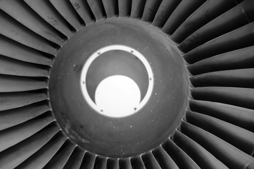
Blend, Polish, and Peen: Extending the Life of Turbine Blades

A turbine blade experiences a combination of heat, high velocities, and continuous vibration. A minor nick or roughness can result in a crack which can quickly impact both performance and availability.
This article describes how blending, polishing and peening work in tandem to control damage and enhance blade life in industrial steam and gas turbines.
Why Blade Edges Are Vulnerable
Blade edges experience the harshest of the flow path environment. Leading edges are the first to experience impact from particles and water droplets. Trailing edges are formed thin and can erode away easily. Thermal cycles (see here for more), corrosion pits and rub events can be stress concentrators with amplification in the case of high-cycle fatigue. When borescopes are used to evaluate the blade or during hot gas path inspections, these are often the first features to have indicators of distress, with the local geometry corresponding to the amplification of stress and airflow.
Controlling those features early in the life of a blade can prevent the defect from migrating into the platform or root, which would then also require repairs, but at a significantly greater expense. Steam units tend to suffer from droplet and carryover erosion, where gas turbine blades rarely take damage from moisture, but may encounter erosion from dust, ash, or foreign object debris from the intake.
What Does Blending Achieve?
Blending eliminates notable notches and returns a smooth contour after minor foreign object damage or tip rubs. It reduces the concentration of stress and stabilizes the risk of crack initiation, while not disrupting the blade’s original aerodynamic design, without changing the radius at the defect. During a minor outage, if damage is within engineering limits and non-destructive testing shows no subsurface crack, teams may complete turbine blend and polish. Typical goals and controls include:
- Restore a smooth and gradual transition matching known profiles for the leading, or trailing edge.
- Limit material removal to maintain wall thickness and chord; confirm with gauges or digital templates.
- The length and depth of blend should not exceed limits explicitly stated in approved repair data; ensure measurements are recorded before and after the work.
- Ensure surface finish is uniform so that downstream polishing can achieve target roughness.
- Where applicable, reinspect using dye penetrant or eddy current to verify defect removal.
Benefits of Polishing for Turbine Parts

Polishing improves the surface finish left by blending and removes micro-scratches that act as stress risers. A smoother finish helps reduce boundary-layer turbulence, hot spots and local oxidation, thus helping retain efficiency between outages. Polishing will also reduce fretting at shrouds and platforms by reducing high points that concentrate load. Polishing can help recoup a controlled amount of heat rate when it is worked in conjunction with hot gas path inspections. Engineers can substantiate that polishing will never flatten profiles or override thinning; the goal is a uniformly textured profile, not excessive stock removal.
How Peening Strengthens Surfaces
Shot peening (https://en.wikipedia.org/wiki/Shot_peening) or micro-peening introduces a thin layer of compressive residual stress at the surface. The thick compressive layer acts against tensile fatigue stresses, such as crack opening at the surface, especially near repaired areas. Many times, repair procedures specifically call for peening after blending and polishing to restore fatigue margin on edges, fillets and tips of turbine blades without changing blade geometry.
Implementation focuses on repeatable coverage and controlled intensity.
- Media size and hardness is specific to a material and location (leading edge vs. platform fillet).
- The intensity of peening is specific to an approved range and verified with Almen strips; All productions should receive up to full coverage in the directed planned intensity.
- Mask dovetail fits, air seals, thin trailing edges, as needed to eliminate distortion and/or over-peening. No masking will yield unplanned exposure and peening of feature, which will result in the blade needing to be removed for a rework.
- Verify a visual inspection of parts, and wherever specified, surface residual-stress verification.
- Within the in-situ repair services, direction of peening would be documented for traceability, aligned with the outage scope.
Industry Best Practices for Blade Care
Successful programs lead all of these blending, polishing, and peening efforts in connected steps within the broader inspection event plan. First, the team reaches a sense of a fairly consistent bore scope evaluation and provides some decisions on if repair or replace is better supported with documented NDT, as needed. Second, engineering ascertains key controls (templates, blend maps, sign off) is observing geometry within limits. Third, engineering collects repair records as a basis of condition-based maintenance collection to ensure intervals and future part planning will reflect real time damage rates, operational fuel type, and filtration performance. Sites inserting the blades in dust or near coast should consider subscriptions shortening inspection intervals since edge wear is quicker.
Finally, the teams also systematically align the organization for improvement into job sequencing, and a focus on cleanliness up to and after blade work is complete. The team procrastinates blatant FOD location, finalizes torque and balance and repeats clearances before close out. With controls in process and clear topoint acceptance criteria, the plant can extend blade life, sustain efficiency/optimization leverage on forced outages without sacrificing reliability.


